- 您现在的位置:买卖IC网 > Sheet目录135 > MBRM560-13-F (Diodes Inc)DIODE SCHOTTKY 60V 5A PWRMITE3


DS30299 Rev. 6 - 2
1 of 4
www.diodes.com
MBRM560
? Diodes Incorporated
NOT RECOMMENDED FOR NEW DESIGN
USE PDS560
MBRM560
5A SURFACE MOUNT SCHOTTKY BARRIER RECTIFIER ?
3
POWERMITE
Features
?
Guard Ring Die Constructi
on for Transient Protection
?
Low Power Loss, High Efficiency
?
Low Reverse Current
?
For Use in Low Voltage, High Frequency Inverters, Free
Wheeling, and Polarity Protection Applications
?
Lead Free Finish, RoHS Compliant Version (Note 2)
Mechanical Data
?
Case: POWERMITE
?3
?
Case Material: Molded Plastic. UL Flammability
Classification Rating 94V-0
?
Moisture Sensitivity: Level 1 per J-STD-020
?
Terminals: Solderable per MIL-STD-202, Method 208
?
Lead Free Plating (Matte Tin Finish).
?
Polarity: See Diagram
?
Marking Information: See Page 3
?
Ordering Information: See Page 3
?
Weight: 0.072 grams (approximate)
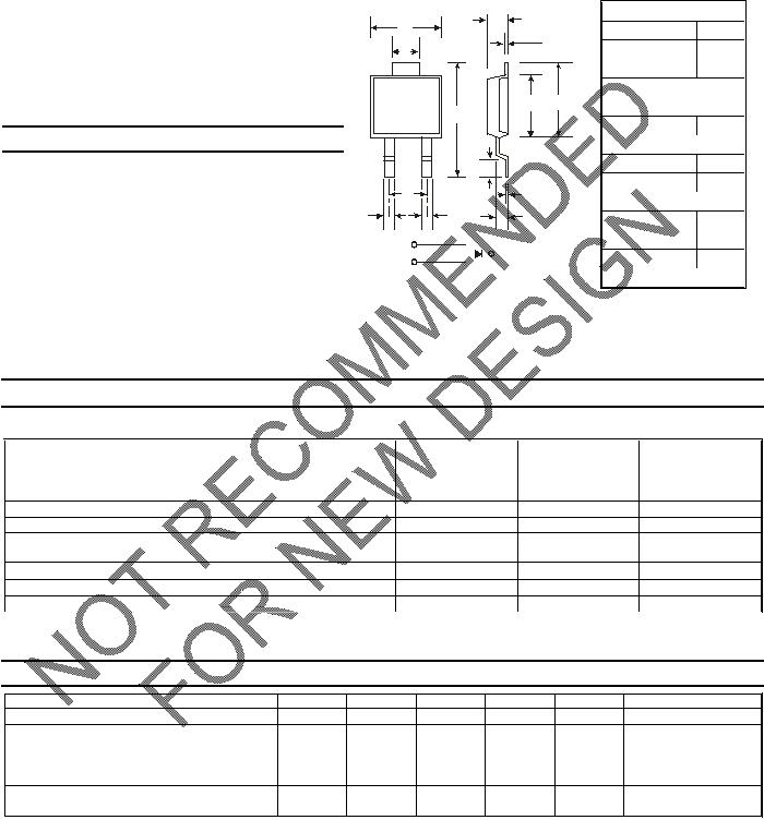
POWERMITE?3
Dim Min Max
A
4.03 4.09
B
6.40 6.61
C
.889 NOM
D
1.83 NOM
E
1.10 1.14
G
.178 NOM
H
5.01 5.17
J
4.37 4.43
K
.178 NOM
L
.71 .77
M
.36 .46
P
1.73 1.83
All Dimensions in mm
Maximum Ratings @T
A
= 25°C unless otherwise specified
Single phase, half wave, 60Hz, resistive or inductive load.
For capacitive load, derate current by 20%.
Characteristic Symbol Value Unit
Peak Repetitive Reverse Voltage
Working Peak Reverse Voltage
DC Blocking Voltage
VRRM
VRWM
VR
60 V
RMS Reverse Voltage
VR(RMS)
42 V
Average Rectified Output Current (See also Figure 5)
IO
5 A
Non-Repetitive Peak Forward Surge Current
8.3ms Single half sine-wave Superimposed on Rated Load @ TC
= 90
°C
IFSM
100 A
Typical Thermal Resistance Junction to Soldering Point
RθJS
2.7
°C/W
Operating Temperature Range
TJ
-55 to +125
°C
Storage Temperature Range
TSTG
-55 to +150
°C
Electrical Characteristics
@TA
= 25°C unless otherwise specified
Characteristic Symbol Min Typ Max Unit Test Condition
Reverse Breakdown Voltage (Note 1)
V(BR)R
60
?
?
V
IR
= 0.2mA
Forward Voltage
VF
?
?
?
?
0.65
0.56
0.74
0.64
0.69
0.60
0.78
0.68
V
IF
= 5A, T
J
= 25
°C
IF
= 5A, T
J
= 125
°C
IF
= 8A, T
J
= 25
°C
IF
= 8A, T
J
= 125
°C
Reverse Current (Note 1)
IR
?
?
2
0.6
200
20
μA
mA
TJ
= 25
°C, VR
= 60V
TJ
= 100
°C, VR
= 60V
Notes: 1. Short duration pulse test used
to minimize self-heating effect.
2. EU Directive 2002/95/EC (RoHS). All applicable RoHS exemptions applied, see EU Directive 2002/95/EC Annex Notes.
Note: Pins 1 & 2 must be electrically
connected at the printed circuit board.
B
C
D
E
G
J
H
K
L
M
A
P
12
3
PIN 1
PIN 2
PIN 3, BOTTOMSIDE
HEAT SINK
C
发布紧急采购,3分钟左右您将得到回复。
相关PDF资料
MBRS130L
DIODE SCHOTTKY 30V 2A SMB
MBRS130
DIODE SCHOTTKY 30V 1A SMB
MBRS140LT3G
DIODE SCHOTTKY 1A 40V SMB
MBRS140
DIODE SCHOTTKY 40V 1A SMB
MBRS1540T3G
DIODE SCHOTTKY 1.5A 40V SMB
MBRS190T3G
DIODE SCHOTTKY 90V 1A SMB
MBRS230LT3G
DIODE SCHOTTKY 2A 30V SMB
MBRS2H100T3G
DIODE SCHOTTKY 2A 100V SMB
相关代理商/技术参数
MBRM760
制造商:DIODES 制造商全称:Diodes Incorporated 功能描述:7A SURFACE MOUNT SCHOTTKY BARRIER RECTIFIER
MBRM760-13
制造商:DIODES 制造商全称:Diodes Incorporated 功能描述:7A SURFACE MOUNT SCHOTTKY BARRIER RECTIFIER
MBRM760-13-F
功能描述:肖特基二极管与整流器 SCHOTTKY RECTIFIER RoHS:否 制造商:Skyworks Solutions, Inc. 产品:Schottky Diodes 峰值反向电压:2 V 正向连续电流:50 mA 最大浪涌电流: 配置:Crossover Quad 恢复时间: 正向电压下降:370 mV 最大反向漏泄电流: 最大功率耗散:75 mW 工作温度范围:- 65 C to + 150 C 安装风格:SMD/SMT 封装 / 箱体:SOT-143 封装:Reel
MBRMBRB1660-E3
制造商:Vishay Intertechnologies 功能描述:MBRB1660-E3
MBRN55D22R1F
制造商:Ohmite Mfg Co 功能描述:
MBRP1-030-01
功能描述:RIVET MINI-BARBED PIN .063" RoHS:是 类别:硬件,紧固件,配件 >> 铆钉 系列:MBR 产品培训模块:Rivets and Hardware
Engineering Technology
Injection Molding and Plastics
Plastic Materials 标准包装:1,000 系列:SR 类型:卡入式 铆钉直径:0.197"(5.00mm) 接头直径:0.354"(8.99mm) 铆钉长度:0.260"(6.60mm) 孔直径:0.203"(5.16mm) 面板厚度:0.098 ~ 0.138"(2.49 ~ 3.51mm) 接头高度:0.087"(2.21mm) 特点:阻燃 颜色:黑 材质:尼龙 其它名称:61100367SRVO-5055 BSRVO-5055 B-NDSRVO5055B
MBRP1-062-01
功能描述:RIVET MINI-BARBED PIN .095" RoHS:是 类别:硬件,紧固件,配件 >> 铆钉 系列:MBR 产品培训模块:Rivets and Hardware
Engineering Technology
Injection Molding and Plastics
Plastic Materials 标准包装:1,000 系列:SR 类型:卡入式 铆钉直径:0.197"(5.00mm) 接头直径:0.354"(8.99mm) 铆钉长度:0.260"(6.60mm) 孔直径:0.203"(5.16mm) 面板厚度:0.098 ~ 0.138"(2.49 ~ 3.51mm) 接头高度:0.087"(2.21mm) 特点:阻燃 颜色:黑 材质:尼龙 其它名称:61100367SRVO-5055 BSRVO-5055 B-NDSRVO5055B
MBRP1-100-01
功能描述:RIVET MINI-BARBED PIN .133" RoHS:是 类别:硬件,紧固件,配件 >> 铆钉 系列:MBR 产品培训模块:Rivets and Hardware
Engineering Technology
Injection Molding and Plastics
Plastic Materials 标准包装:1,000 系列:SR 类型:卡入式 铆钉直径:0.197"(5.00mm) 接头直径:0.354"(8.99mm) 铆钉长度:0.260"(6.60mm) 孔直径:0.203"(5.16mm) 面板厚度:0.098 ~ 0.138"(2.49 ~ 3.51mm) 接头高度:0.087"(2.21mm) 特点:阻燃 颜色:黑 材质:尼龙 其它名称:61100367SRVO-5055 BSRVO-5055 B-NDSRVO5055B
